

CNC Machining for Robot Structural Parts: From ±0.01 mm Prototype to Production
How robotics OEMs use 3-, 4- and 5-axis machining to hold critical fits, cut development risk, and scale from one prototype to a thousand units.
Why the structure, not the software, decides whether a robot ships
Most robot programs do not fail on control logic. They fail at the interfaces: a joint housing that will not seat, a motor mount that drifts under load, a wrist flange whose mating face loses flatness after anodizing. Every one of those problems is a machining problem, and all of them are cheaper to solve in aluminum than in a production mold.
That is why CNC machining remains the backbone of robot development. It turns a CAD model into a part in the final material - aerospace-grade aluminum, titanium, stainless steel, magnesium, or a high-strength engineering plastic - with enough accuracy to test the real assembly, not a stand-in. The same process then carries the program through pilot builds until volumes justify tooling.
At Shenzhen Strongd Model Technology, robotics accounts for 48% of revenue. The parts we machine most are not decorative: quadruped robot structural sets, humanoid joint modules, industrial arm links, dexterous-hand components, and sweeper robot chassis parts.
1. What CNC machining actually solves in a robot program
CNC machining covers computer-programmed milling, drilling and turning. In practice it answers four questions that decide a schedule:
Does the design assemble? Functional prototypes machined from the production alloy expose interference, stack-up and fastener problems before tooling is cut.
Does it survive the duty cycle? Real material shows real stiffness, damping and wear behavior; a 3D-printed shape does not.
Can we test end-use parts? Low-volume bridge parts let you put units in front of customers while molds are still in design.
Can we change our mind? A design revision on a machined part costs a new program. A revision after mold steel is cut costs weeks.
Our batch range runs from a single prototype to 1,000-piece pilot runs, then into injection molding when the volumes and the cost curve justify it.
2. Start with the load path, then choose the material
Material selection in robotics is a mass-and-stiffness argument, not a catalog lookup. Moving mass at the end of a kinematic chain multiplies torque demand at every upstream joint, so the useful question is always: how much stiffness per gram, and at what cost?
|
Material |
Where it earns its place |
Watch-outs |
|
Aerospace-grade aluminum |
Arm links, joint housings, quadruped frames; best stiffness-to-weight for most structural parts |
Anodize build-up on mating faces; thread wear in soft alloy |
|
Titanium |
High-load joints, wear-critical pivots, weight-critical brackets |
Tool wear, longer cycle time, higher cost per part |
|
Stainless / carbon steel |
Shafts, wear surfaces, high-strength brackets |
Mass penalty; corrosion protection needed |
|
Magnesium alloy |
Weight-critical housings |
Chip-handling and fire-safety controls in the shop |
|
Engineering plastics (ABS, PC, PA, PMMA) |
Covers, brackets, low-load housings, cosmetic parts |
Creep under sustained load; thread inserts required |
A useful discipline: define the datum scheme and the two or three dimensions that set the fit before choosing the process. Everything else can move; those cannot.
3. The tolerances that matter - and the ones that don't
Tolerance on a drawing is a cost driver, and most drawings carry more of it than the assembly needs. The dimensions worth tightening are the ones that set fit and function:
Critical fit dimensions: ±0.01 mm. Bearing bores, joint interfaces, motor pilots, dowel locations.
Repeat positioning accuracy: ±0.01–0.05 mm across a batch, which is what determines whether part 400 still drops into the fixture that accepted part 1.
100% CMM inspection on key dimensions, rather than sampling. Sampling tells you the batch is probably fine. Gauging every critical feature tells you which parts are fine, and gives you the report to prove it.
Everything else - cosmetic surfaces, non-mating outlines, clearance holes - should be toleranced to the process that makes it cheapest.
4. Where 5-axis earns its cost
Five-axis machining is often sold as a capability. It is better understood as a setup-reduction tool, and setup count is where accuracy and lead time are actually lost.
A humanoid joint module typically has bores on two or three non-parallel axes, a deep internal pocket, and a sealing face that must stay flat. On a 3-axis machine that is three or four setups, each one a chance to re-clamp and re-indent a datum. On a 5-axis center the part is cut in one clamping: the bores stay concentric to each other, the sealing face stays perpendicular to the bore axis, and the fixture never gets a second chance to be wrong.
The economics follow. Fewer setups mean shorter queue time, less fixturing, and fewer scrapped parts at the last operation - which matters most on the expensive materials, where a titanium housing scrapped at OP40 is a costly lesson.
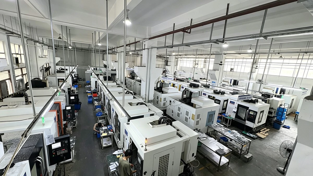
Our floor runs 85 CNC machining centers, including 18 five-axis machines (10 Mingcheng/Tianche, 8 Hardinge) and 6 CNC lathes. We machine magnesium alloy and aerospace-grade aluminum, titanium, stainless steel and brass, and we finish parts ready for polishing, plating or painting.
5. DFM feedback before the spindle turns
The cheapest mistake to fix is the one caught on a screen. Every drawing we receive goes through a manufacturability review at no extra cost, and the review is specific to robot hardware rather than generic:
Wall thickness and pocket depth against tool reach and deflection, especially in long arm links.
Corner radii that let a standard cutter reach the floor of a pocket without a second operation.
Thread depth and insert strategy in aluminum, where thread pull-out is a common field failure.
Cable routing and sensor pockets that must survive assembly, not just exist in CAD.
Mating-face flatness after surface treatment, including anodize and coating build-up.
Fixture and datum planning, so the tolerance stack in the drawing matches the one the machine can actually hold.
If a feature cannot be made at the quoted price, we say so before production rather than after.
6. The process ladder: prototype, pilot, production
Choosing the process is a volume decision, and the transition points are predictable. What should not change between steps is the datum scheme and the inspection criteria.
|
Stage |
Process |
Typical volume |
What it is for |
|
Concept validation |
Industrial SLA / SLS / MJF 3D printing |
1–20 pcs |
Form, fit in assembly, appearance models |
|
Functional prototype |
3-, 4- or 5-axis CNC machining |
1–50+ pcs |
Real material, real loads, design sign-off |
|
Bridge / pilot |
Vacuum casting from silicone molds |
10–50+ pcs per mold |
Sales samples and pilot builds before tooling |
|
Low-volume production |
CNC machining |
50–1,000 pcs |
End-use parts, high-mix programs |
|
Mass production |
Injection molding / die casting |
1,000+ pcs |
Unit-cost reduction at stable design |
Two practical notes. First, vacuum casting is a bridge, not a destination: it buys time to validate the market before committing to steel. Second, the handoff from machined prototype to molded part is where tolerances drift, because shrinkage, gate location and cooling all move dimensions. Keep the same critical-feature list and re-qualify the first molded samples against it.
7. Inspection is a process, not a final gate
A single outgoing inspection catches defects late, when rework is most expensive. Our quality chain runs seven stages: incoming material inspection, process review by a three-person team averaging 18 years of experience, production planning from drawings and CMF requirements, in-process inspection against sample drawings, engineering review of appearance and structure, project follow-up with a daily 4:30 pm progress meeting, and outgoing inspection against drawings before shipment.
The metrology behind it includes Hexagon CMM (TESA-MH3D-DCC) and automatic 2D vision measurement, 2.5D vision systems, X-ray inspection, colorimeter and light-transmittance testing, plus environmental chambers, UV and salt-spray testers, and simulated transport vibration. For robot parts, the combination matters: dimensional conformance gets a part into the assembly, and environmental testing predicts whether it stays there after a year in the field.
Certifications: ISO 9001:2015, IATF 16949:2016, CE, RoHS, and a 2023 SGS factory audit.
8. Lead times, and what to send for a quote
Quotation: preliminary solution with price, lead time and DFM suggestions within 8 working hours of receiving drawings.
CNC and 3D-printed prototypes: typically 3–7 working days depending on complexity; rush options available.
Vacuum casting: 5–10 working days.
Molds: 15–25 working days, with injection production scheduled per MES.
To quote accurately on the first pass, send:
3D files (STEP / IGS / STL).
2D drawings with tolerances and GD&T.
CMF requirements - color, material, finish.
Quantity and target batch size.
Target lead time and delivery destination.
Acceptance criteria and any special packaging or shipping instructions.
Missing 2D drawings are the most common cause of a slow quote. A STEP file defines geometry; it does not define which bore is a bearing fit and which is a clearance hole.
9. Six questions worth asking any CNC partner
Which dimensions will you inspect at 100%, and will I get the report?
How many setups does this part need, and where is the datum?
What is your DFM feedback loop, and is it free before PO?
What happens if parts arrive out of spec - remake, rework, or credit?
How do you protect my IP, and will you sign an NDA?
At what volume should we move this part to molding, and who owns that transition?
The short version
Robot structural parts are a tolerance-and-interface problem. Machine the parts that set fit in the final alloy, hold ±0.01 mm where the assembly actually needs it, inspect every critical feature rather than a sample, and move to tooling only when volume pays for it. Do that, and the mechanical side of the program stops being the schedule risk.
About the manufacturer
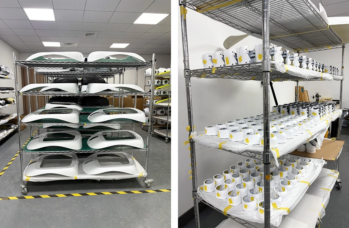
Shenzhen Strongd Model Technology Co., Ltd. was founded in 2012 and provides one-stop manufacturing for robot structural parts: CNC machining, 3D printing, vacuum casting, thermoforming, mold making and injection molding, die casting, sheet metal fabrication and surface finishing. The 40,000 m² facility in Bao'an District, Shenzhen runs 85 CNC machining centers, 130 injection molding machines from 120T to 800T, and a full metrology lab. The company holds ISO 9001:2015 and IATF 16949:2016 certification, has exported for 14 years, and has served more than 10,000 enterprises.
Website: https://www.strongdcnc.com/


