

Humanoid robot prototyping succeeds or fails on how well each part family is matched to the right process. Appearance shells need smooth surfaces and fast cosmetic iteration, which favors SLA printing and vacuum casting; structural frames need stiffness and real material properties, which favors CNC machining from aluminum; joint housings and actuator components need precision bores and repeatable fits, which puts them in machined metal even at low volumes. Teams that treat all parts as one category end up paying mold-tool prices for parts that will change next week, or shipping demo units with visibly unfinished shells. This guide breaks the humanoid robot into its three part families, shows which process fits each stage from first mock-up to pilot production, and explains how to iterate without wrecking the schedule.
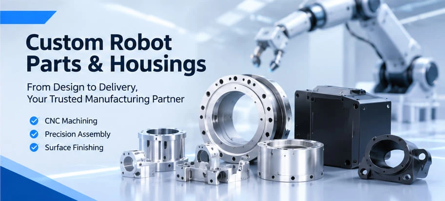
What Humanoid Robot Prototyping Actually Covers
A humanoid robot is three different engineering problems wearing one body. The first family is appearance parts: shells, covers, and head enclosures that define what customers, investors, and the press actually see. The second is structural parts: torso frames, limb skeletons, and mounting plates that carry loads and hold alignment. The third is joint and actuator components: motor housings, harmonic-drive mounts, and rotating joint brackets where bearing bores and tolerances decide whether the robot moves smoothly or fights itself.
The distinction matters because each family fails differently. A cosmetic defect on a shell is embarrassing; a deflection problem in a structural frame is dangerous; an out-of-round bore in a joint housing quietly destroys a bearing over weeks of testing. Procurement teams that segment their request for quotes by part family get faster responses and more accurate prices than teams that send one undifferentiated drawing package.
Appearance Shells: Harder Than They Look
Robot shells look simple and are not. They are large, thin-walled, doubly curved, and they show every flaw: flow lines, sink marks over internal ribs, sanding scratches under gloss paint, and parting lines in places no mold designer wanted to put them. On a humanoid robot the shell is also usually split into front and rear halves around openings for arms, cable routing, and service access, which makes seam quality a design decision, not an accident.
For early units, SLA printing with careful sanding and priming produces convincing form-and-fit shells in days. Once the design stabilizes enough to need five to fifty units - for a demo fleet, a trade-show run, or a pilot line - vacuum casting from a silicone mold becomes the efficient route: it reproduces the master's surface faithfully, supports engineering resins with credible paint adhesion, and avoids injection tooling while the design is still moving. Injection molding belongs at the point where the design is frozen and quantities justify steel. If you are weighing those two routes for shells specifically, our vacuum casting versus injection molding comparison walks through the cost crossover in detail.
- Design shells with deliberate seam lines and matching fastener bosses, so split-line quality is controlled instead of improvised
- Keep critical cosmetic surfaces out of the mold's parting direction, or accept polishing and rework on every unit
- Specify paint and texture on reference panels before volume finishing begins - a shared physical standard ends most finish arguments
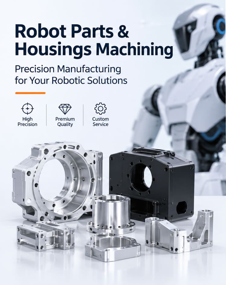
Structural Parts: Where Metal Beats Plastic
Structural frames carry the loads that shells only pretend to carry: actuators bolted through them, batteries mounted inside them, and arms cantilevered off them. Printed plastic frames work for tabletop demonstrations, but sustained walking or manipulation loads expose the limits quickly - creep at bolted joints, flex that misaligns sensors, and fracture at sharp internal corners.
CNC machining from aluminum plate or billet is the default for structural prototypes and early production, most commonly 6061 for general frames and 7075 where strength-to-weight really matters. Machining delivers the real material, real fastener preload, and real thermal behavior the engineering team needs to validate - not an approximation of them. Geometry rules are the same ones that govern any machined part: uniform wall thinking, generous internal radii, through-features planned for tool access. Our guide to CNC machining tolerances covers what is worth specifying on joint-critical features versus what is wasted cost.
Joint and Actuator Components: Precision Under Load
Joint components are the smallest parts on the robot and the least forgiving. A shoulder or hip joint housing typically pairs a motor and harmonic drive with bearings seated in machined bores; if those bores wander from round or from position, the joint binds, wears unevenly, or leaks backlash into every motion. These are precisely the parts that should stay machined metal - usually aluminum, occasionally stainless - even when overall volumes are far too small to justify molds.
Practical guidance for robot teams: consolidate joint-critical tolerances onto a short feature list (bearing bores, seal faces, drive-mounting pilot surfaces) and hold the rest at standard machining tolerances; plan datums so that prototype parts and later molded or cast parts measure against the same reference; and machine joint components in the same batch as structural fittings so their alignment is verified on real hardware, not on paper. When volumes grow, many programs keep joint housings machined permanently - low-volume machining of high-value precision parts is frequently cheaper than qualifying a die-cast alternative that must then be finish-machined anyway.
Process Selection by Stage: One-Offs, Bridge, Production

The stage-by-stage pattern below keeps money where the design is still moving and moves it to tooling only when the design has earned it.
| Stage | Typical quantity | Appearance shells | Structural and joint parts |
|---|---|---|---|
| Concept and form study | 1–3 units | SLA printing, sanded and primed | Machined fittings as needed for stiffness |
| Functional prototype | 3–10 units | SLA or CNC-machined plastic shells | CNC machined aluminum, real material testing |
| Demo fleet and pilot line | 10–50 units | Vacuum casting from silicone molds, painted | CNC machining, batch-produced |
| Production ramp | 500+ units | Injection molding after design freeze | Die casting or continued machining, by cost study |
Iteration Discipline: The Real Schedule Risk
On humanoid programs, the schedule is rarely broken by any single process - it is broken by redesign loops that arrive without warning. A shell change late in the paint stage costs a repaint; a joint housing change late in assembly costs re-machining plus a new alignment check. The teams that ship on time treat iteration as a budgeted resource: they freeze the joint-critical geometry first, because it drives the electrical and motion stack; they let appearance shells iterate longer, because surface processes recover easily; and they run physical prototypes at every stage boundary rather than trusting CAD interference checks alone.
Choosing a partner for this pattern means choosing one that can move parts between processes without re-teaching them the design. Suppliers who run printing, machining, casting, molding, and finishing in-house can carry a single datum scheme from the first machined prototype to the molded production shell - our article on how robot programs run end to end describes that hand-off discipline in detail, and our robot enclosure manufacturing guide goes deeper on shell-specific decisions. For teams still selecting a partner, the questions worth asking are about process transitions, not machine counts: how a design change propagates, who owns the tolerance stack across processes, and what happens to inspection reports when a part changes process family.
Frequently Asked Questions About Humanoid Robot Prototyping
How long does it take to build the first physical prototype of a humanoid robot?
With machining and printing in-house, machined structural fittings and printed shells typically take days to about two weeks depending on geometry, which is fast enough to support a real assembly-and-test loop. Full assembled robots take longer because sourcing actuators, batteries, and electronics usually dominates the schedule - mechanical prototyping is rarely the bottleneck.
Can vacuum cast shells survive real product testing?
For demo units, trade shows, and pilot user testing, cast polyurethane shells with proper paint are generally convincing and adequately durable. They are not equivalent to injection-molded engineering resins for impact resistance, UV stability, or long-term wear - cast parts are a bridge, and teams should plan the transition to molding once quantities and design stability justify it.
Why not 3D print structural frames instead of machining them?
Industrial printing in nylon and composites works for some brackets, but layer orientation, anisotropic strength, and creep under sustained load make printed frames a gamble for primary structure. Machined aluminum gives the real stiffness, real fastener behavior, and predictable fatigue performance a walking robot's frame must demonstrate - and for most frame geometries it is also faster than printing and finishing an equivalent part.
What tolerances matter most on humanoid robot joints?
Bearing bore diameter and roundness, seal and pilot face concentricity, and the position of drive-mounting features relative to the bearing axis. Everything else on a joint housing can usually stay at general machining tolerances. Over-tolerancing non-critical features raises machining cost with no performance gain - the tolerances guide explains how to draw that line.
How many prototype iterations should we budget before production tooling?
It varies by program, but the useful discipline is per part family: freeze joint-critical geometry after functional testing, allow shells to iterate through at least one full demo cycle before committing to molds, and gate every tooling decision on a quantity forecast rather than optimism. A supplier who asks about your iteration plan during quoting is doing you a favor, not delaying it.
Humanoid robots reward teams that match every part family to the right process at the right stage - and punish the ones that pour everything into tooling before the design has settled. If you are planning prototypes or a pilot build, request a quote with your drawing package and process questions, and our engineers will review each part family against your stage and quantity.
Related: our vacuum casting versus injection molding comparison | our article on how robot programs run end to end | our robot enclosure manufacturing guide | the tolerances guide | request a quote


