

Metal 3D Printing: When It Wins, and When It Is Expensive Theatre
Metal additive is a real production process. It is also the most misapplied one in the shop - chosen for parts that a machining centre would make faster, cheaper and more accurately. Here is how to tell the difference.
What the process actually is
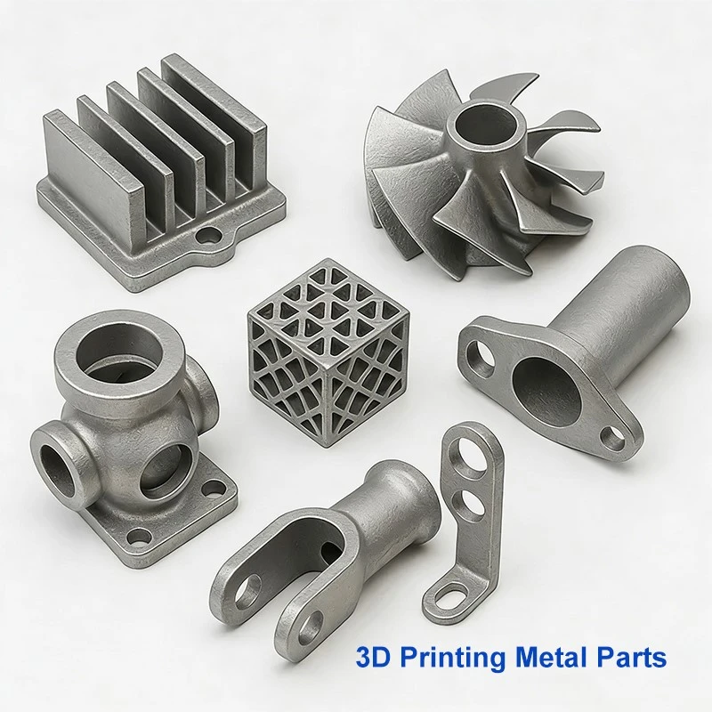
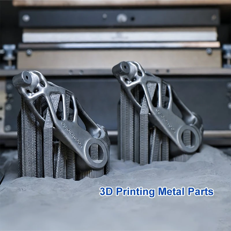
Almost every "metal 3D printed part" you have held was made by laser powder bed fusion (LPBF, also sold as SLM or DMLS). A thin layer of metal powder, typically 20–60 µm, is spread across a plate. A laser melts the cross-section of the part. The plate drops. Another layer goes down. Repeat a few thousand times.
That is the whole idea. Everything difficult about the process follows from it: the part is built in slices, it is built inside a bed of powder, and it cools at rates that weld metal normally never sees.
|
Process |
How it works |
Where it fits |
|
Laser powder bed fusion (LPBF) |
Laser melts each layer in a powder bed |
The default for complex, small-to-medium parts |
|
Electron beam melting (EBM) |
Electron beam in vacuum, hot process |
Titanium orthopaedics, less residual stress |
|
Directed energy deposition (DED) |
Powder or wire fed into a moving melt pool |
Large near-net shapes, repair, cladding |
|
Binder jetting |
Binder printed into powder, then sintered |
High volume small parts, lower cost, more shrinkage |
Four processes, four different design rulebooks. This article is mostly about LPBF, because that is what most enquiries mean.
The cost curve is vertical, not by weight
This is the single fact that changes how you design for metal AM.
In machining, cost tracks the material you remove and the time the spindle runs. In LPBF, cost tracks build height and the area the part occupies on the plate. A 200 g part sitting 150 mm tall costs far more than a 400 g part lying 40 mm tall. Weight is almost irrelevant; the machine charges you for vertical space and for the seconds each layer takes.
Three consequences:
1. Lay it down. Re-orient the part so its smallest dimension is vertical, and the price can halve.
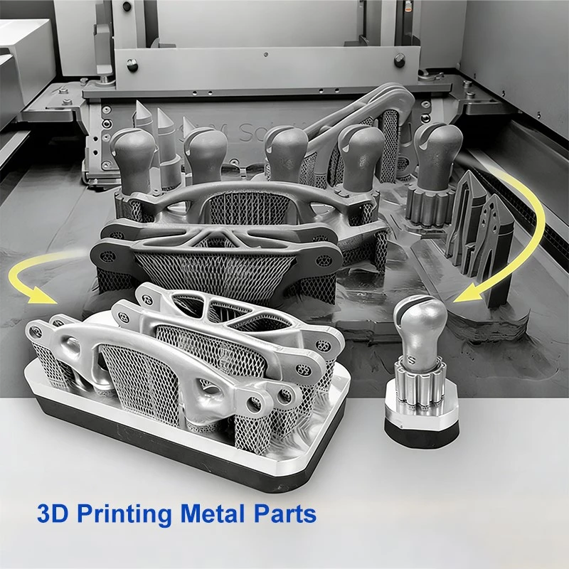
2. Fill the plate. Ten parts in one build spread the fixed cost - powder, gas, machine time, one heat treatment - over ten parts. One part alone on a plate carries all of it.
3. Design for the build, not for the drawing. If two parts can share a build by being nested or stacked, that is a cost decision made at the design review.
A supplier who quotes metal AM by weight has not understood their own process.
Five signals that metal AM is the right answer
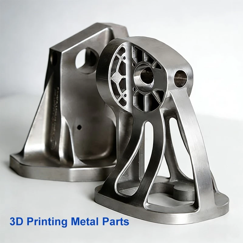
Internal channels that cannot be drilled. Conformal cooling in a mould insert, cooling jackets around a motor, fuel galleries inside a manifold. This is the strongest case, and it has no competitor.
Topology that would need five setups. Organic, load-following shapes with undercuts on every face. Machining them means fixturing each face; printing means one build.
Consolidation. Twelve machined parts, brazed and bolted into one assembly, become one printed part with no joints to leak or fret.
Very small quantities of a complex part. One to fifty pieces of something that would need a casting tool. No tool, no minimum order.
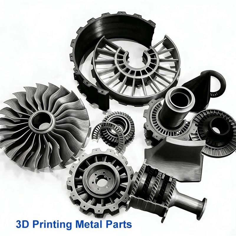
A material that is miserable to machine. Titanium and some nickel alloys cut slowly and wear tools; printing near-net and machining only the interfaces can be cheaper than cutting from solid.
Five signals that it is not
The part is basically a block with holes. A machining centre will be faster, cheaper and tighter. Printing it is a way to pay four times more for worse tolerances.
Tolerance matters everywhere. LPBF holds roughly ±0.1 mm, or ±0.2% on larger dimensions, and it varies with orientation. If the whole part needs ±0.02 mm, you are printing a blank and machining it anyway.
Hundreds or thousands of pieces. Beyond a few hundred, casting or forging plus machining wins on unit cost, and metal powder is not cheap.
Large and simple. Build volume is the limit, and a big simple part uses the most expensive real estate in the factory.
Mirror surface or a sealing face as built. As-printed surfaces run around Ra 8–12 µm. Anything better is a machining or polishing operation afterwards.
|
Metal AM (LPBF) |
CNC machining |
Casting + machining |
|
|
Complexity |
Almost free |
Costs setups and time |
Costs tooling |
|
Geometry freedom |
Highest |
Limited by the cutter |
Limited by draft |
|
Tolerance |
±0.1 mm typical |
±0.01 mm on critical features |
Needs machining allowance |
|
Surface as supplied |
Ra 8–12 µm |
Ra 1.6 µm or better |
Ra 12 µm, then machined |
|
Quantity sweet spot |
1–200 |
1–1,000 |
500+ |
|
Lead time |
Days per build |
Days |
Weeks for tooling |
|
Material waste |
Low, but powder handling |
High, chips |
Medium |
The alloys, and what each one is for
|
Alloy |
Character |
Typical parts |
Post-processing |
|
AlSi10Mg |
Light, castable-grade, good thermal |
Housings, heat sinks, brackets |
Stress relief, optional T6, often machined |
|
Ti-6Al-4V |
Strong, corrosion-proof, expensive powder |
Aerospace brackets, implants, medical instruments |
Stress relief, HIP, machining |
|
316L stainless |
Ductile, corrosion resistant, forgiving |
Manifolds, food and chemical parts |
Stress relief, passivation |
|
17-4PH |
High strength after ageing |
Tooling, functional prototypes, aerospace fittings |
Solution and age, HIP optional |
|
CoCr |
Wear and temperature resistant |
Medical implants, turbine and wear parts |
HIP, heat treat, polishing |
|
Inconel 718 |
High temperature strength |
Hot-section aerospace, energy |
Stress relief, HIP, ageing |
|
CuCrZr |
High thermal and electrical conductivity |
Induction coils, heat sinks, welding electrodes |
Heat treat, machining |
Two rules of thumb from this table: aluminium is the easiest entry point and the least forgiving on distortion; titanium and nickel are where printing pays for itself, because the alternative is slow cutting.
Design rules that actually decide success
|
Feature |
Rule |
Why |
|
Overhang |
Support needed below about 45° from vertical |
Unsupported melt sags and curls |
|
Minimum wall |
Around 0.4 mm, 0.6–1.0 mm for load-bearing |
Thin walls distort and are hard to clean |
|
Minimum hole |
Around 0.5–1.0 mm, and only through-holes |
Small bores close up and trap powder |
|
Powder escape |
Every hollow needs at least two openings |
Trapped powder is a reject, and a hazard |
|
Channel size |
1.5 mm and up for reliable powder removal |
Narrow channels block during cleaning |
|
Clearance for mating parts |
Extra 0.1–0.2 mm on printed fits |
Printed surfaces are rougher than machined |
|
Sharp internal corners |
Add radii |
Stress concentration plus unmelted powder |
|
Datum faces |
Design them flat and machinable |
They will be machined, so plan for it |
The powder escape rule catches more first-time designers than any other. A closed hollow with one small hole looks fine on screen and arrives full of metal powder, or gets drilled open by the supplier - at your cost.
Distortion, stress and heat treatment
LPBF welds metal in thousands of tiny passes. Each pass shrinks as it solidifies, and the part resists. The result is residual stress, which shows up as:
Warping when the part is cut off the plate.
Cracking in stiff, thick sections - particularly in nickel alloys and tool steels.
Movement during machining, so the finished part drifts out of tolerance days later.
The standard answer is a chain, not a single step:
1. Build with support and anchors so the part cannot curl while printing.
2. Stress relief before removal from the plate, in the furnace, while still attached.
3. Remove from the plate by wire EDM or saw, not by force.
4. HIP where the application justifies it - titanium and nickel in fatigue or pressure service. HIP closes internal porosity, but it also moves the part, so it belongs before final machining.
5. Heat treat to the alloy's specification, then machine the datums.
Skipping step 2 is the most common cost-saving mistake, and it usually shows up at the customer, not at the supplier.
After the printer: the part is half finished
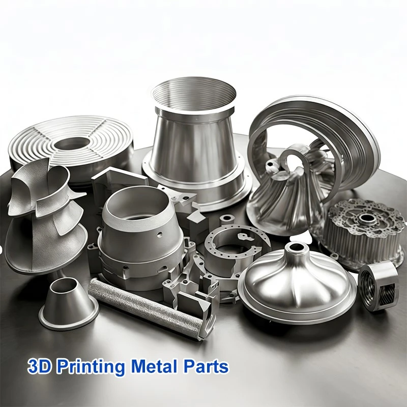
An as-printed part is a near-net shape. The finishing chain is where the money and the schedule actually go:
Support removal by hand tools, or by machining for critical surfaces.
Wire EDM off the plate to preserve the base flatness.
CNC machining of datums and interfaces - bearing bores, seal faces, threads, dowel holes. This is unavoidable for any part that mates with something else.
Surface finishing by bead blasting, vibratory finishing, polishing or anodising, depending on the alloy.
Cleaning, especially internal channels: ultrasonic, flow check, and for medical or vacuum parts, a documented procedure.
This is why metal AM parts so often come back to a machining centre. The printer makes the shape; the machining centre makes the part usable.
Inspection: what to check, and how
Density and porosity - by CT or by destructive section on a witness coupon built with the part.
Internal channels - CT is often the only way to confirm a conformal cooling passage is clear and correctly formed.
Dimensions - CMM on machined features; optical or structured light on freeform surfaces where a probe cannot reach.
Mechanical properties - test coupons built in the same orientation as the part, because orientation changes the result.
Powder and residue - a cleanliness check, particularly for channels and for medical or food-contact parts.
What to send with an enquiry
1. The 3D model, as a solid, with the build orientation you have in mind if you have one.
2. The alloy, and whether an equivalent is acceptable.
3. Which features will be machined after printing, and to what tolerance.
4. The load case or the function - pressure, fatigue, thermal cycling - because it decides heat treatment and HIP.
5. Quantity per year, and whether the part could be redesigned for the process.
6. The inspection and acceptance rules, including any CT or coupon requirements.
That list is short, and most enquiries arrive with only the first item.
About the manufacturer
Shenzhen Strongd Model Technology Co., Ltd. is a CNC machining and industrial 3D printing supplier for robotics, automotive, medical and consumer electronics customers. The Shenzhen plant covers 40,000 m² and runs 85 CNC machining centres, 18 of them five-axis, alongside nine industrial polymer printers with builds up to 1,500 × 750 × 550 mm. Inspection uses Hexagon CMM under ISO 9001:2015 and IATF 16949:2016. Prototypes ship in 3–7 days; quotations are returned within 8 working hours.
Website: https://www.strongdcnc.com/


